Basics and Core Concept: A Precise Switch That Guards the Start
Definition and Role
The starter relay is essentially an electromagnetically controlled current amplifier. Its main job is to use the small current from the ignition switch (usually <1A) to control the large current (200–300A) going to the starter motor. This design creates a key link between the battery and the starter motor, and also protects the expensive ignition switch from early damage caused by high current.
Main Types
Standard single-contact relay: Simple and reliable. It is the lowest in cost and widely used in economy cars.
Integrated relay module: Often built into the fuse box (common in Japanese cars). It saves space, but requires full module replacement during repair.
Solid-state relay: The third-generation smart starter relay uses semiconductor technology. It has no mechanical contacts, lasts over 300% longer, handles high current impacts better, and shortens start-up response by 40%. This is the main choice for luxury and new energy vehicles.
Core Functions
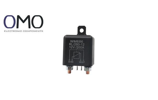
Besides amplifying current, the relay also provides voltage drop compensation (keeps voltage stable during large current startup) and safety isolation. The case shows standard terminal labels (85/86 for control coil, 30 for constant power input, 87 for output to starter motor). These are globally used.
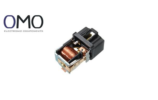
Working Principle
When you turn the key to “Start” (or press a button), a small current flows through terminals 85 and 86. The coil creates a magnetic field that pulls in the armature. This closes the main contacts between 30 and 87, allowing strong battery current to flow to the starter motor. The engine starts. Once the key is released, the magnetic field stops, the spring opens the contacts, and the start process ends.
Location and Identification: Quickly Find Your Current Commander
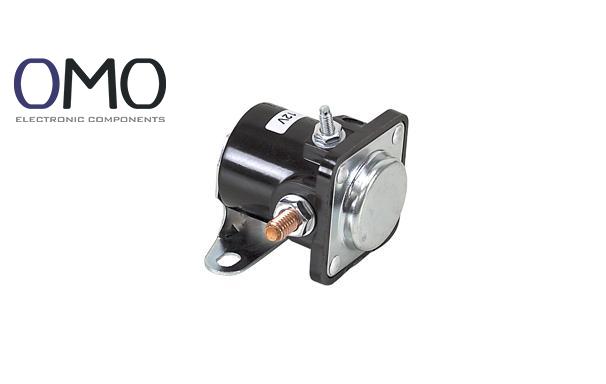
Visual Features of Starter Relays
Shape: Plastic cube (common size: 2.5cm x 3cm)
Pins: 4-pin (most common) or 5-pin design
Label: Often marked “STARTER”, “S”, “STR”, or “启动” (Start), or shows current rating (e.g., 30A)
Position: Usually in the engine bay fuse/relay box
Typical Mounting Locations
Location Area
Common Car Models
Notes
Engine bay main fuse/relay box
VW, Buick, Toyota
Near battery and starter, 70% of cases
Dashboard side/footwell fuse box
Honda, Nissan, some German cars
Requires removing panels
Firewall (engine side), standalone
French cars, old American cars
Good cooling but exposed to engine heat
Failure Signs and Diagnosis: Spot the Silent SOS
Common Failure Symptoms (Watch for These!)
Total silence: Turn key but nothing happens; dashboard lights are normal.
Hard to start: Need several tries before engine starts.
Noises: “Click” or “buzz” sound from relay during or after starting.
Root Causes of Failure: Why the Relay Stops Working
Electrical Killers
Contact burning: Frequent starts or high current cause arcs. Contacts melt or oxidize. Tests show: one 200A arc raises contact surface to 1000°C. Cheap materials fail after ~100 starts (risk >78%).
Coil open circuit: Long-term heat ages and cracks the wire coating.
Terminal oxidation/loose: Moisture, fluid leaks, or vibration increase resistance and block current.
Environmental Damage
High heat: Engine bay >85°C speeds up plastic aging and coil breakdown. Life shortens by 50%.
Moisture corrosion: Rain or car wash causes rust. In coastal areas, fault rate rises by 35%.
Vibration damage: Engine shaking can break solder points or wire connections.
Mechanical Fatigue
Stuck armature: Dirt or rust blocks moving parts.
Spring failure: The return spring weakens and loses force.
Seal damage: Broken seal lets dirt or moisture inside.
Accurate Testing: Hands-On Health Check
Basic Tool Kit
Digital Multimeter (DMM): Must-have! Checks resistance, voltage, and continuity.
12V Test Light: Quickly checks power and signal.
Relay Tester (optional): Simulates real use, one-click full test. 3× faster.
Static Test (Relay Not Working)
Test coil: Set multimeter to 200Ω range. Measure between pins 85 and 86. Normal is 50–120Ω. Too low = short. Too high or ∞ = open circuit.
Test contacts: Measure between pins 30 and 87. Should show “OL” (open circuit). If connected, contact is stuck.
Dynamic Test (Simulate Working)
Power test method:
Connect relay pin 85 to battery +.
Connect pin 86 to battery –. Relay should “click”.
Immediately measure resistance between pins 30 and 87. It should be <0.5Ω (full conduction). Test should be <5s to avoid overheating.
Bypass test (Warning: Emergency Only!):
Use a thick wire to touch both 30 and 87 terminals in the relay socket. (This forces current to the starter). If the engine starts, the relay is faulty. Be very careful to avoid sparks or shorts!
Replacement and Maintenance: Smart Ways to Extend Life
Replacement Steps (Safety First!)
Power off: Disconnect the battery’s negative cable.
Locate and record: Find the bad relay. Record the model and direction (use photo or mark it).
Remove: Use relay puller tool to pull straight up (don’t pry and damage the socket).
Install: Make sure the new relay matches specs. Align with key slot and press down fully.
Test: Reconnect the battery and start the engine to check.
Preventive Maintenance Tips
Regular checks: Every 2 years or 30,000 km, check for burnt marks or corrosion on case or pins.
Socket tightening: If socket is loose, use fine tools to slightly pull copper contacts tighter.
Protection upgrade: Spray electrical contact protector on clean relay pins and socket.
Top-grade spray forms a self-healing anti-arc film, resists >200°C, blocks oxidation, and doubles lifespan.
Smart Selection Tips
Current rating: Choose a relay rated ≥ factory spec (recommended ≥30A).Models with silver alloy contacts handle 45% more current shock and reduce arc damage by 70%.
Protection level: Use IP67 waterproof relays in engine bay (survives 30 min in water).
Code check: Match OEM numbers (e.g., Bosch 0 332 019 150, Hella 4RA 007 113-01) for 100% fit.
Frequently Asked Questions
What does a starter relay do?
The starter relay, positioned between the vehicle's battery and the starter motor, serves as a protective switch. It regulates electrical current flow to enable efficient and safe engine starting, while also safeguarding other electrical components from potential damage.
What is a starter relay?
In a vehicle's starting system, the starter relay acts as an electronic switch, regulating the high-amperage current delivered to the starter motor.
Where is starter relay located?
While the starter relay's mounting location varies depending on the model, common installation points include: near the fuse box in the engine compartment, a specific zone within the engine compartment, or the cab/chassis relay box.
How does a starter relay work?
Electromagnetic induction and contact control enable the starter relay's function: a small current accurately controls a large current.