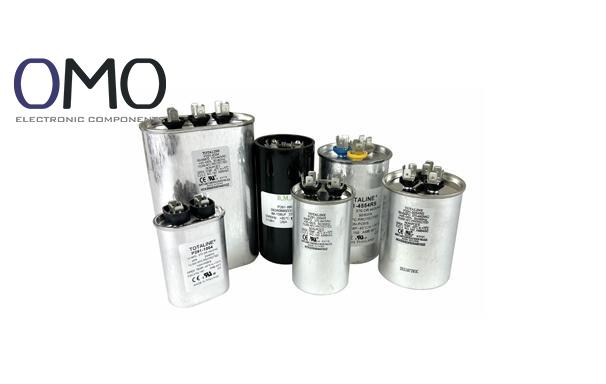
An AC Capacitor is a non-polarized energy storage component designed for AC circuits.Its working principle is based on electromagnetic field interaction. When AC voltage is applied across the capacitor, the dielectric inside charges and discharges periodically under forward and reverse voltage.This process not only stores and releases energy but also makes the current phase lead the voltage phase by about 90 degrees.This phase difference gives AC capacitors an irreplaceable role in many fields.
Key Functions
Motor start and run: In a single-phase induction motor, the auxiliary winding provides a phase-shift current, creating the rotating magnetic field for startup (start capacitor). During running, it improves the power factor (PF), reduces reactive losses, and increases efficiency (run capacitor).
Power factor correction (PFC): In power grids or devices, it compensates for inductive loads (like motors, transformers). This improves efficiency and reduces line loss.
Signal processing: In filter circuits, it bypasses or removes interference signals of certain frequencies (like EMI/RFI), keeping devices stable.
Key Features and Parameters
Designed for AC: Clearly marked with rated AC voltage (VAC, e.g., 440VAC) and frequency (50/60Hz).
Key materials: Polyester (PET), polypropylene (PP), metallized film, or oil-paper. Each suits different needs.
Reliable performance: Metallized film gives self-healing ability. After local breakdown, insulation can recover automatically.
Non-polarized: Can safely withstand forward and reverse AC voltage.
Key Parameters (Selection Basis)
Parameter
Description and Meaning
Unit/Example
Rated AC Voltage (VAC)
Maximum safe RMS AC voltage
250VAC, 440VAC, 600VAC
Capacitance
Ability to store charge
μF (microfarad), e.g. 5μF, 50μF
Rated Frequency
Designed AC frequency
50Hz, 60Hz, 50/60Hz
Tolerance
Allowed difference from nominal value
±5%, ±10%, ±20%
Operating Temperature
Safe working range
-40°C ~ +85°C, +105°C
Loss Tangent (tan δ / DF)
Lower value = less energy loss, higher efficiency, lower
Ideal <0.001 (e.g. PP film)
Applications
AC capacitors are used widely in industry and daily life.
Single-phase induction motors (main use):
Start capacitor: Gives strong starting torque (large capacitance, tens to hundreds μF). Works only for seconds and then disconnects by a centrifugal switch.
Run capacitor: Stays in the circuit. It improves power factor (often +0.2 to 0.3), increases efficiency, and reduces current and losses.
Lighting systems: Used in fluorescent and HID (high-intensity discharge) lamp ballasts. They give start pulses and improve PF.
Power quality management: Used for PFC in large systems. They reduce reactive power, lower line losses, and improve supply capacity. ROI is often less than 2 years.
Coupling/Bypass: Transfers signals or bypasses noise in amplifiers and communication devices.
Voltage protection: Suppresses surges or spikes to protect sensitive components.
Refrigeration/air-conditioning compressors: Provide necessary support for motor startup and running. Dual capacitors are designed for this.
Types of AC Capacitors
By Function
Start Capacitors:
Task: Provide short high current for strong starting torque. Work only for a few seconds.
Features: Large capacitance (tens to hundreds μF). Mostly non-polarized aluminum electrolytic type (low cost, short use). Larger in size.
Run Capacitors:
Task: Work continuously during motor running. Improve power factor, efficiency, and stability.
Features: Smaller capacitance (few to tens μF). Usually polypropylene film (low loss, long life, reliable). Strong continuous current ability.
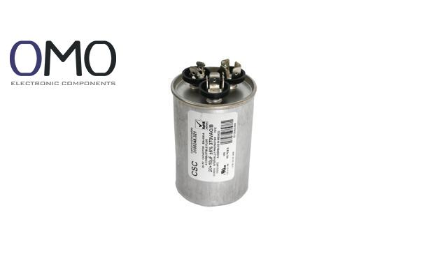
Dual Capacitors:
Function: Combine start and run functions in one unit, often for air conditioners.
Structure: Three terminals: C (common, often line), FAN (fan motor, smaller value), HERM (compressor motor, larger value). Usually metal-case, oil-filled, good cooling.
By Dielectric/Structure
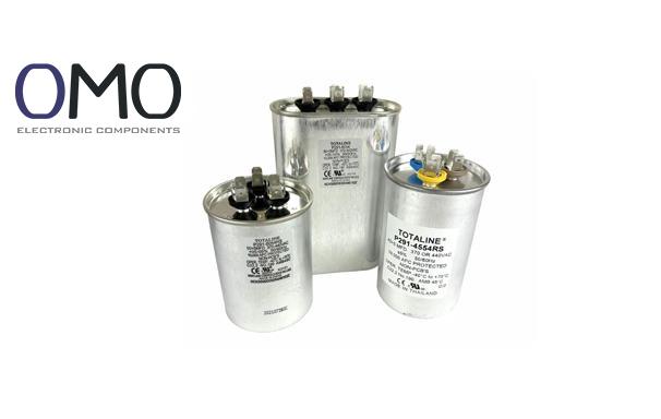
Film Capacitors (main choice):
Features: Use PET, PP, or metallized film.
Advantages: High accuracy, self-healing, very low loss, very long life. Best for run, filter, and PFC use.
Aluminum Electrolytic Capacitors:
Features: High capacitance per volume, low cost.
Limits: Mainly for starting use (short time). Higher ESR, larger loss (tan δ), shorter life. Less reliable, especially in high temperature.
Oil-filled Capacitors:
Features: Filled with insulating oil.
Advantages: Excellent cooling. Used in high-power tasks (motors, compressors). Common in dual capacitors needing high current and high voltage.
AC vs DC Capacitors: Essential Differences
Clear distinction between AC and DC capacitors is critical for safety.
Feature
AC Capacitor
DC Capacitor
Design
For pure AC or strong AC environment
For constant DC or small AC ripple
Voltage Rating
Marked as VAC (e.g. 440VAC)
Marked as VDC
Polarity
Non-polarized
Usually polarized (electrolytic); some non-polar types (ceramic, film)
Structure
Symmetric dielectric; metallized film self-healing
Polarized DC types cannot take reverse voltage (may explode)
Main Parameters
VAC, frequency, μF, tan δ
VDC, μF, leakage current, ESR
Common Materials
PP, PET, metallized film, oil-paper
Electrolyte (Al, Ta), ceramic, PP, PET, mica
Self-healing
Common (esp. metallized film)
Only in some non-polar film types
PF Function
Key function
Not main function
Terminals and Color Codes (For Reference Only)
Safety Note: Color codes are not global standards. Always follow capacitor label (C, FAN, HERM, 1, 2) and device wiring diagram.
Single capacitor, two terminals (non-polarized): Both terminals equal. Labels may be C & FAN, H & HERM, or 1 & 2. Wire colors vary. Connect as per old capacitor.
Dual capacitor, three terminals (mainly for AC units)
C (Common): Connect to line (L). Wire often Red or Purple.
FAN: Connect to fan motor winding. Wire often Brown, Yellow, or Black.
HERM: Connect to compressor motor winding. Wire often Yellow or Orange.
Start capacitor (non-polarized): Two terminals are the same. Wires usually same color (e.g., two brown, two blue).
Safe Replacement of AC Capacitors
Replacing a failed AC capacitor is common but dangerous due to high voltage. Follow safety rules:
Power off completely: Disconnect power (plug out, breaker off). Use a tested voltmeter to confirm no AC voltage remains.
Discharge capacitor:
Capacitors may hold charge for minutes or hours.
Use a discharge tool or insulated screwdriver to short both terminals (expect spark/sound).
Safer: Use a resistor (5–10kΩ, >5W) in series to discharge slowly.
Confirm with voltmeter: 0V across terminals.
Mark old wires: Before removal, take a photo or label wires with their terminal names (C, FAN, HERM).
Remove old capacitor: Carefully detach wires and remove capacitor.
Check and install new capacitor:
Match capacitance (μF). Must be same as original (within tolerance).
Rated AC voltage (VAC): Must be equal or higher than original (never lower).
Connect wires exactly as before. Terminal markings (C, FAN, HERM) are more important than wire colors.
Fix the capacitor securely inside the equipment.
Final check and test:
Ensure all wires are firm, no exposed copper.
Power on and check if motor/fan/compressor starts smoothly.
Listen for abnormal noise or vibration. Measure current if possible.
Frequently Asked Questions
What color wires go to an AC capacitor?
Brown wires are typically connected to the herm (H) terminal for the compressor, black wires to the common (C) terminal, and yellow wires to the fan (F) terminal for the condenser fan.
Where does the orange wire go on an AC capacitor?
Although wiring colors for AC capacitors vary by manufacturer and application, with no universal standard for orange wire, in a typical HVAC system it usually connects to the capacitor's common (C) terminal.
Does it matter what way you wire a capacitor?
While non-polarized capacitors don't care about orientation, reversing the polarity on polarized capacitors (e.g., electrolytic, tantalum) can cause serious damage or even cause them to explode.
What do the colors of the AC power wire mean?
In AC power wiring, wire colors designate function: black and red wires are hot, white or gray wires indicate neutral, and green or bare copper wires are for grounding.